Remote Monitoring FAQs
Remote Monitoring Resource and Troubleshooting Guide
Monitoring Systems
System Selection
What Instrumentation woud you recommend?
uWave Monitoring Systems recommends the Micromate®, Minimate PRO4 or Minimate Plus when monitoring 1-3 parameters such as Vibration, Air Ovrepressure and Noise.
Sensor Selection
What Sensors would you recommend?
Sensor selection is often job specific. uWave Monitoring Systems always recommends that you read and understand the job specifications before selecting a sensor. Please contact us if you need help with sensor selction.
Remote Station Setup
Unit Setup
What remote configuration would you recommend for monitoring construction with the Micromate®?
The following configuration is optimized for construction remote monitoring on the Micromate®, Minimate PRO, Minimate Plus and Blastmate III units:
- Record Mode Histogram Combo
- Interval Length ≥ 1 minute
- Record time (fixed) ≤ 5 seconds
- Sample rate 1024
- Trigger level ≥0.2 in/s
Also keep in mind the following tips to increase your data integrity when monitoring with a DC power system:
- Monitor during daylight hours.
- Use the modem relay/warm up time when immediate alerts are not required. This requires the use of additional equipment.
Using this configuration will increase the reliability of your data transfers by keeping your file sizes smaller and reducing the number of files to a manageable size for reporting.
Sensor Setup
How do I setup the sensors with my remote monitoring station?
The triaxial ISEE or DIN geophone should be placed inside the remote station unless you are using an extension cable to monitor away from the base station. If you are spiking the geophone to the ground, screw the three ground spikes into the bottom of the geophone or sandbag the geophone if you are unable to use the ground spikes. If you are close to the vibration source and expect that the sensor may decouple from the surface, you should bury the geophone approximately 6 inches taking care to keep the geophone level.
Always refer to the ISEE Field Practice Guidelines for the appropriate methods of seismograph setup.
Battery Setup
What kind of battery do I need for the remote station and how do I set it up?
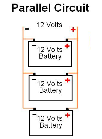
The typical remote station uses either one or two 12 volt batteries to provide power to the cellular gateway (modem) and/or backup power for the seismograph or data logger. You may chose to wire two or more batteries in parallel to increase the capacity of the batteries. When wiring batteries in parallel always use batteries of the same type, voltage and capacity in amp hours(Ah).
Sealed Lead Acid (SLA) Absorbent Glass Mat (AGM) batteries are recommended in remote solar powered installations due to their outstanding performance in demanding applications as well as being spill proof and maintenance free.
For short duration monitoring in areas with good solar insolation or sun hours/day and with low data transmission rates you may use a smaller capacity battery such as 18 Ah
For long term monitoring or monitoring in areas with poor solar insolation and or large data transmission requirements you should choose one or more 30 Ah batteries to in order to maintain data integrity.
Batteries Plus has nationwide stores if you get in a jam or you can order online. We recommend their Werker Deep Cycle 12 volt 35 Ah battery.
Batterywholesale.com also has a wide selection of Universal brand batteries.
Your local ACE Hardware store may also have 12 volt Universal batteries.
When preparing to setup your 12 volt battery you should follow these simple conventions. Batteries are polarized which means they have a positive and a negative side. The positive side of the battery is usually marked with a '+' and typically has the color red associated with it. The negative side of the battery is normally marked with a '-' and has the color black associated with it.
Always connect positive to positive and negative to negative or you may damage some of the electrical components in the installation.
uWave Monitoring Systems uses the following components and polarity color schemes in the remote monitoring station:
- Solar Panel- Positive(red OR white), Negative(black)
- Charge Controller IN- Positive(yellow), Negative(black)
- Charge Controller OUT- Positive(red), Negative(black)
- Seismograph Power Adapter- Positive(red OR black w/white stripe), Negative(black)
- Timer Wiring Harness- Positive(white/red), Negative(black)
Solar Panel Setup
How do I setup and connect the solar panel?
uWave Monitoring Systems uses a 30 watt solar module that measures 26.25 inches x 16.25 inches x 1 inch thick. The solar module does not have a built in blocking diode and thus requires a solar charge controller to prevent overcharging the battery and discharging the battery back through the solar panel at night.
The remote station you purchase or rent may or may not have the solar panel connected to the solar panel bracket on the remote station. Most of MMC's remote stations are prewired with a charge controller and power adapter for the seismograph. You should purchase or plan on purchasing a 12 volt battery for use with the system.
uWave Monitoring Systems uses the following components and polarity color schemes in the remote monitoring station:
- Solar Panel- Positive(red OR white), Negative(black)
- Charge Controller IN- Positive(yellow), Negative(black)
- Charge Controller OUT- Positive(red), Negative(black)
- Seismograph Power Adapter- Positive(red OR black w/white stripe), Negative(black)
- Timer Wiring Harness- Positive(white/red), Negative(black)
Where should I setup the solar panel?
If your solar panel is attached to the solar panel mounting bracket on the remote station, your solar panel will be setup at the monitoring location. In order to convert the sun's rays into electrical energy, the solar panel must be facing the sun and should be unobstructed from receiving direct sunlight.
Solar Panel DONT'S
- DONT place the solar panel behind buildings, under trees on in areas with a lot of shade.
- DONT point the solar panel to the north in the northern hemisphere.
- DONT expect 2 hours of direct sunlight to keep your batteries charged.
If you need to monitor in a shaded area, the remote station should be placed in an area with direct sunlight and you should use an extension cable for your geophone.
Wiring Diagrams and Setup Intructions
Do you have any wiring diagrams or setup instructions that I can reference?
Programmable Timer Wiring Harness
Remote Station Troubleshooting
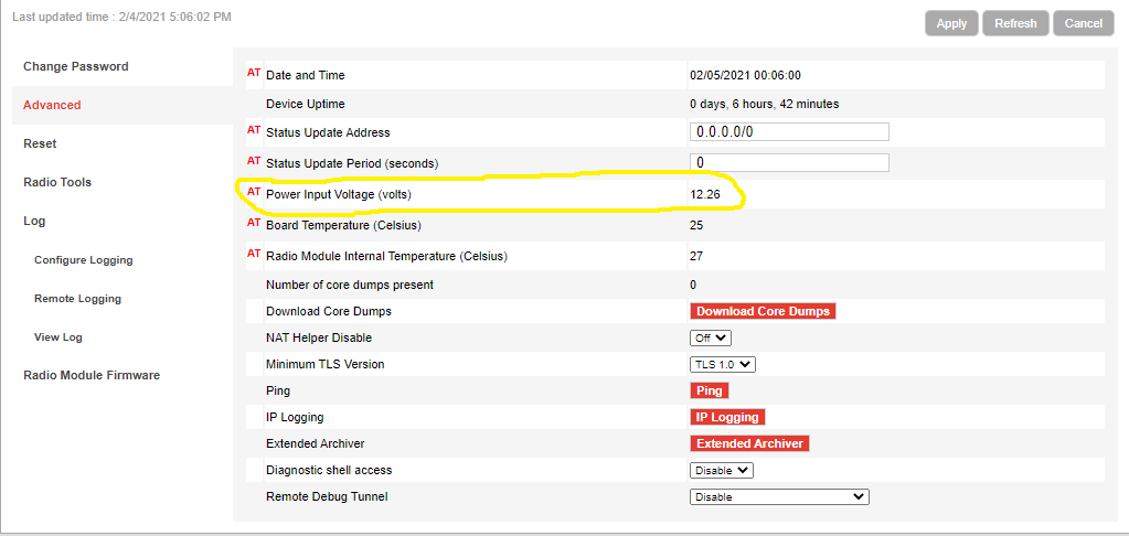
How do I remotely check the external battery voltage for my remote station?
uWave users can check the modem voltge in the modem table under Assets > Modems.
Using a web browser log into the modem using the IP address and port 9191 for http access or 9443 for https access. For example http://166.123.123.123:9191 or https://166.123.123.123:9443
Enter your username and password, if you do not see the login screen, the modem is most likely offline or you do not have access through the modems firewall. Once you login, click the Admin tab then click the Advanced tab. Look for the power in voltage setting.
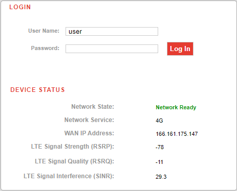
How do I check the cellular signal strength or RSSI (received signal strength indicator)?
uWave users can check the modem LTE signal strength (RSRP) in the modem table under Assets > Modems.
On newer style RV class modems the RSSI or RSRP may be displayed on the Device Status Screen which appears on the Login screen. If you don't see the RSSI or RSRP diplayed on the Login screen, login to the modem and the RSSI or RSRP is displayed on the Home Status page.
Modems
Modem Recommendations
What modems do you recommend?
uWave Monitoring Systems uses and recommends Sierra Wireless Airlink Gateway Products. The RV55 LTE Industrial Gateway is the current recommended modem for use with all Instantel monitoring products.
Antennas
What antenna should I use with my modem?
uWave Monitoring Systems currently uses the PCTEL GNSS + Cellular antenna GNSMB-COV supplied by Anaconda Networks
Connecting Antennas
Where do I connect my antennas to the modem?
uWave Monitoring Systems recommends connecting the antenna according to the manufacturers recommendtions.
Refer to the RV55 Quick Start Guide.
What about the GPS antenna?
If you need to use the GPS functionality of the modem connect the GPS antenna to the GPS port on the modem.
Modem/Seismograph Interface Cables
What interface cables do I use with the modems?
The modem or null modem cable used to connect the seismograph to the modem depends on the seismograph you are using.
uWave Monitoring Systems recommends the following modem cables or components:
- Instantel Micromate® - DTECH DT-5011 USB to Serial Adapter Cable
- Instantel PRO4/PRO6
- Minimate PRO Null Modem Cable - Instantel P/N 720A3401
- Minimate PRO Serial Cable - Instantel P/N 720A3101 with the following converters:
- Serial Coupler
- Null Modem Adapter
- Minimate PRO Ethernet Cable - Instantel P/N 720A4101 ****DOES NOT SUPPORT AUTO CALL HOME FEATURE AT THIS TIME**** A future firmware update for the PRO units may support Auto Call Home.
- Instantel Series III Minimate Plus or Blastmate III - custom cable supplied by uWave Monitoring Systems
- Instantel Series I or Series II seismographs do NOT support modem communications.
Modem Power
How do I power the modem?
The Sierra Wireless Airlink Gateways do not have their own internal power supply, an external 7-36 volt DC power must be supplied for the modem to operate.
If you have line power to your monitoring location AC adapter kits are available and are the recommended method of powering the modems.
If an off-grid solar or battery installation is required please contact uWave Monitoring Systems, LLC for current recommendations on powering your modem.
Modem Power Management
How do I configure the modem power management options?
The RV series modems have power management configuration options that will help optimize your external battery life. The RV55 User Guide is a great reference for Power Management
Modem Power Connections and Installation
How do I connect the power to the modem and what are the installation options?
Refer to this section of the RV50 User Guide for modem installation options and connector pinouts Power Connection Guide
Modem Lights (LED) Operation
How do I know the modem is operating properly, what do the lights mean?
Refer to this section of the RV50 User Guide for modem LED operation Modem Lights (LED) Operation
Power
AC Power
How do I power the remote station, seismographs or modems using AC Power?
Alternating Current (AC) power or line power is the most reliable method of powering the remote station components. When possible always use AC power at 110-120 volts to power your remote station.
AC adapters (AC/DC transformers) are available for the seismographs and the modems. Please let us know that you plan on using AC power so we provide the correct power adapters.
If you are using an extension cord to power the equipment make sure that you will be able to connect two AC adapters per seismograph/modem combination.
DC Power
What about DC power?
Direct Current (DC) power is provided by the solar panel and 12 volt battery in the remote station. While this method is less reliable than AC power, with the proper power management plan you should be able to achieve a high level of data integrity.
Batteries and Power Management
I keep running my batteries down, is there a better way to maintain battery life?
The seismographs have their own internal batteries so if you are properly using the solar panel you should not have much trouble with the seismograph power. If you are running a backup 12 volt battery for the seismograph this should be a separate battery than the battery used to power the modem.
Keep in mind that battery intensive monitoring modes such as Histogram and Histogram Combo will drain the seismograph battery very quickly and that you should also use the internal Timer mode in the seismograph if you plan on using Histogram or Histogram Combo modes. If you need to take 24 hour data in Histogram or Histogram Combo, we recommend that you use AC power. If you are unable to use AC power you should have a heavy duty backup battery for the seismograph only.
What about the modem battery, I keep my modem on all the time, is this a problem?
If you are running your modem battery down you probably need to take a closer look at how long you are keeping the modem on.
For most monitoring projects you will only need to transmit data once or twice a day. Depending on the type of modem you are using you should only turn the modem on during the transmit times, possibly one other time for troubleshooting.
If you are using a RV series modem you should use the internal relay in the modem combined with the modem power controlled by relay setting in the AutoCall Home setup of the seismographs. Using this method, the modem is only turned ON when the seismograph triggers it to send data. Keep in mind that you must allow a warmup time of at least 2 minutes for the modem to turn ON and initialize before any data can be transmitted.
Sensors
Geophones
What type of geophone should I use?
In 95% of applications you should use a triaxial geophone (ISEE standard) with a frequency response of 2-250 Hz. The maximum recommended cable length for this sensor is 250 feet (75 m).
On occasions where you need a wider frequency response or need a longer cable run you should use the triaxial geophone (DIN 45669-1 Class 1) with a frequency repsonse of 1-315 Hz and a maximum cable run of 3,280 feet (1,000 m).
We recommend the High frequency triaxial geophone for near-field monitoring. The high frequency geophone has a particle velocity range up to 100 inches/second (2.54 m/s), a frequency response of 28Hz-1kHz and a maximum cable length of 3,280 feet (1,000 m).
Microphones
Why type of microphone would you recommend for monitoring air overpressure?
For most blast monitoring and pile driving monitoring the standard linear air overpressure microphone is recommended. The linear air overpressures range is 88-148 dB(L) (0.000073-0.075 psi(L)).
For measuring high overpressures we recommend the High Pressure microphone which measures air overpressure up to 184 dB(L) (5.0 psi(L)) in the frequency range 5Hz-1kHz.
What about sound monitoring?
For sound monitoring with Instantel seismographs there are two options:
Option 1 uses the Series III Minimate Plus or Blastmate III to do peak only sound monitoring between 50-110 dB(A). Typically this in not adequate for most sound monitoring but may be used to monitor pile driving in some situations.
Option 2 utilizes the Micromate® or Series IV MinimatePRO4 and the Instantel Type 1 Sound Level Meter. This professional grade sound level meter offers complete sound monitoring and paired with a geophone the MinimatePRO4 can do both sound monitoring and vibration monitoring simultaneously on the same unit.
Hydrophones
I need to monitor water pressure using a hydrophone. What would you recommend?
The Instantel Minimate PRO4 and MinimatePRO6 have a hydrophone option. The Instantel hydrophone measure up to 47 psi (324 kPa) with a frequency range of 8-500 Hz. The advanced software module is required. Click here for full specifications.
Remote Alarm Controllers
What are your rental rates for Remote Alarm Controllers?
We have currently have Micromate® Remote Alarm Controllers for rent for $75/month. They are also available for purchase for both Series III, Series IV and Micromate® Instantel seismographs. Usually a cellular modem that allows for alerts via SMS text messaging or email is a more practical way to alert stake holders that a predetermined threshold has been exceeded.The Instantel Series III Remote Alarm Controller is compatible with both the Minimate Plus and the Blastmate III.
The Series IV Remote Alarm Controller is compatbile with the Minimate PRO4 and Minimate PRO6.
The Micromate® Remote Alarm Controller is compatbile with the Instantel Micromate®. NOTE - Micromate® must have the optional AUX port installed to use the Micromate® Remote Alarm Controller
Instantel Remote Alarm Controllers contain a double relay which will control a Warning and an Alarm setting. Typically these relays are used to control an external load such as a siren or a flashing light or both. The maximum load is 24 volts, 2 amps. A common misconception is that the Remote Alarm Controller contains a power source and a flashing light or siren. The power source, which is typically a 12 volt or 24 volt battery is not included. A siren or flashing light is not included. Keep in mind that a construction site is extremely noisy due to the operation of heavy equipment and a siren is usually only going to add to the noise. If you have a plan that involves a highly visible flashing or strobe light the Remote Alarm Controller may be an option.
The light/siren does not stay on very long, how can I fix this?
For Series III (Minimate Plus and Blastmate III) users, keep in mind, that you will only be able to keep the light on for a short period of time unless you are using Histogram only mode. In this case, the relay will keep the light/siren on for the duration of the current Histogram interval.
If you are using Continuous or Histogram Combo mode the light/siren will only stay on for the duration of the waveform event. You may need to increase your waveform record time. NOTE - Series III unit typically have 13 seconds of waveform memory available in Histogram Combo mode - this may be the maximum ON time for your light/siren.
If you are using AutoCall Home, the relay that activates the light/siren will turn off when the unit starts the AutoCall Home process. Using, the "Monitor while calling home" feature will not alleviate the problem as you will not have sufficient waveform memory to record additional events.
Micromate® and PRO instrument users will be able to set a Hold time for the Warning and Alarm relays on the Remote Alarm Controller, however you must also use the "Monitor while calling home" feature to insure the light stays on for the duration of the hold time setting.
Blastware
Unit - Communications - Local
How do I communicate with the unit and download events?
The easiest way is to connect the RS-232 cable to your serial port, typically COM1. Make sure that you have the correct COM port selected under Unit>Communications and that your baud rate is correct. The default baud rates are 38400 for Minimate Plus and Blastmate III units and 115200 for Micromate®®, Minimate Pro4 and Pro6 units.
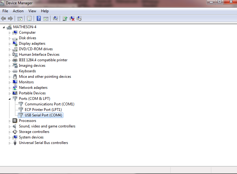
If you are using a USB-Serial Adapter then you will need to make sure you have installed the USB-Serial Adapter correctly. It should show up in the Windows Device Manager as USB Serial Port with a COM port number. If you do not see this in your Device Manager you most likely do not have the driver installed correctly. Make sure you have permission to install drivers on your PC before proceeding. The Device Manager is typically located under Control Panel>System.
The seismograph must be set to Direct communications and the baud rate setting must match the Blastware baud rate settings.
Unit - Communications - Remote
How do I communicate with the unit and download events over a remote connection?
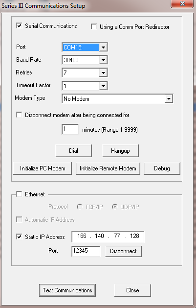
Make sure you have the latest version of Blastware. Under Unit>Communications select Modem Communications. Keep in mind that for security reasons you may not be able to access your unit directly. If you are leasing a modem and data service from MMC please contact us for information on accessing the unit directly.
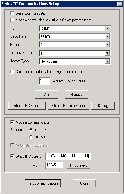
You may need to click the Test Communications button and wait for confirmation or failure of the connection more than once before communications are established. Once you have established communications, start with Unit>Status or Unit>Monitor.
Status will show you important information regarding the Unit's current status. In many situations, this is sufficient to check the unit without disrupting the current monitoring. The status menu shows the current firmware version, calibration date, current date and time on the unit clock, current mode, battery level, memory usage and event count.
Monitor will show the Monitor Status Menu. This is where you Start and Stop Monitoring. You must Stop monitoring before making changes to the Compliance Setup or AutoCall Home setup. When you finish making configuration changes you must return to the Monitor Status window and Start monitoring before end communications with the unit.
Export to ASCII
How do I export an event to a text file?
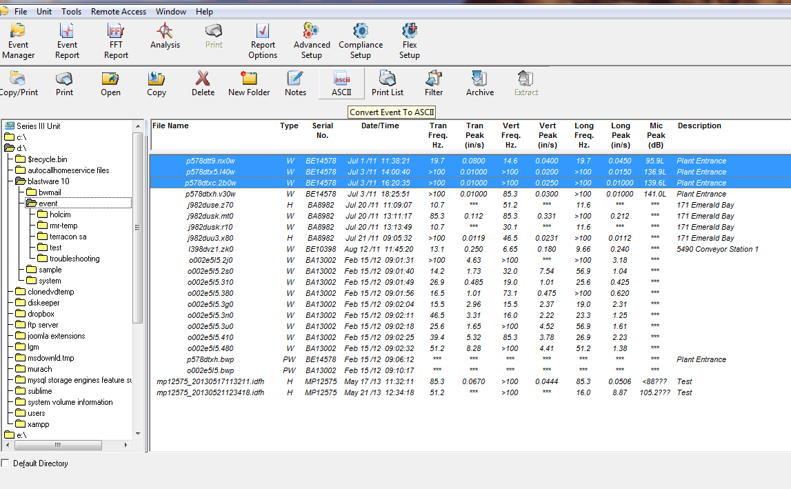
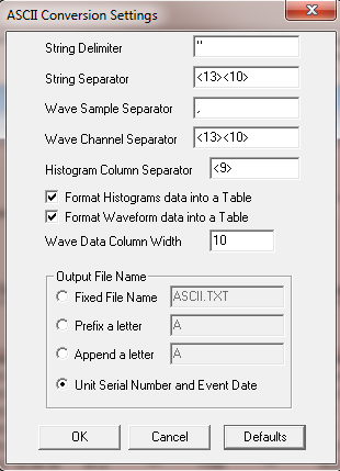
Select the event or events that you want to export to an ASCII formatted text file. Click the ASCII button.
Select the directory to save the ASCII files to. This directory must exist. Blastware will not create a directory automatically.
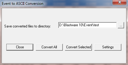
Click Settings to view and or edit the ASCII conversion settings. If you don't understand these settings, see section 4.3.4 ASCII Conversion in the Blastware Manual. When the settings are correct click OK. Click Convert All to convert all the events in the current directory to ASCII or Convert Selected to convert the selected events only.
Post Event Notes
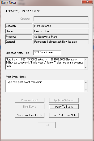
How do I append notes to an event after it has been recorded?
Select the event or events to which you would like to apply post event notes. Click the Notes button in the Event Manager. This will display the Event Notes window. Type the notes you want to add in the Post Event Notes text box. Click Apply to Event to apply the notes. Click Save Post Event Note to save the notes or Load Post Event Notes to load a previously saved note. If you have more than one event selected you can click on Previous Event or Next Event to go to the previous or next event. Click Exit when you are finished adding notes.
Scheduler - Micromate®
How do I use the Scheduler on the Micromate®?
The scheduler is used to increase the flexibility of the Micromate® and uWave Monitoring Systemsrecommends using the scheduler for all remote monitoring applications. Please note that the scheduler can be setup using Blastware or THOR. THOR is recommended, please refer to the THOR - Scheduler section on this page. This may be done locally or remotely.
The scheduler is accessed by first connecting to the Micromate® using Blastware. Then choose Compliance Setup>Special Setups. At the top of the Special Setups tab you will see an Edit button for the Monitor scheduler. Click Edit to access the Monitor Scheduler.
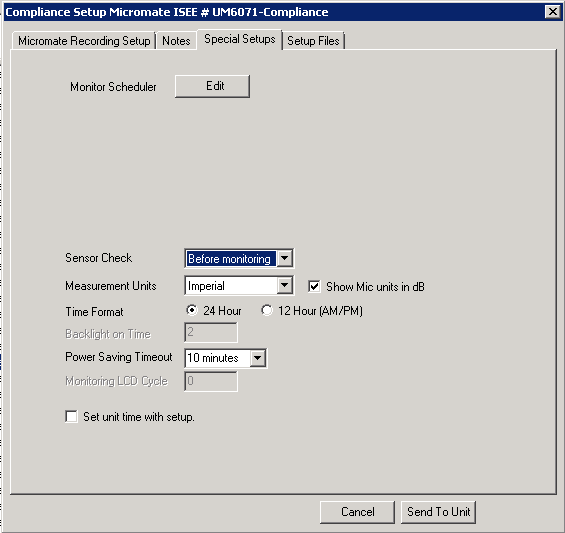
This will bring up the scheduler that is currently on the Micromate®, keep in mind that this may be blank if the scheduler has not be configured previously on your Micromate®. If you get an error such as "Timeout Waiting on Response from Unit!", you will need to exit out and reload the Compliance Setup.
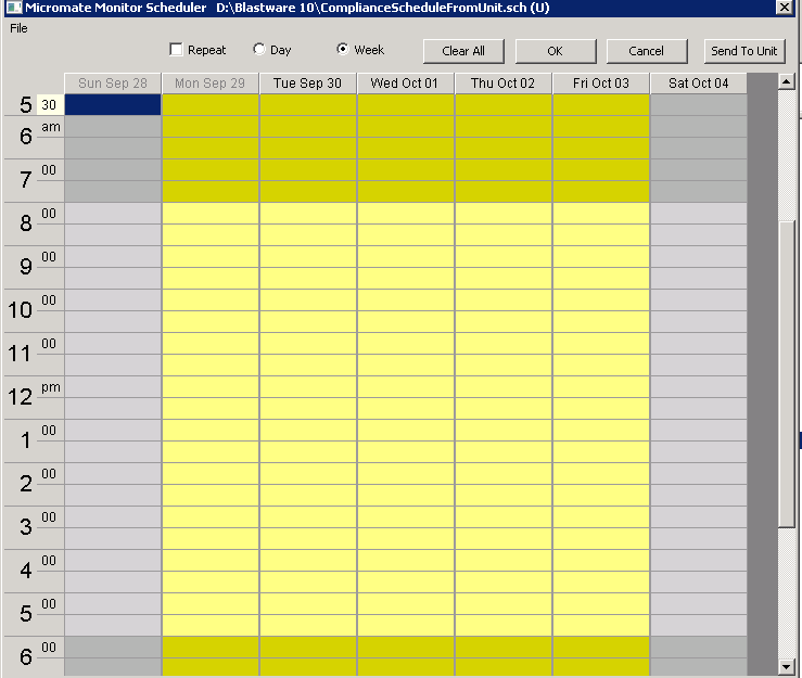
For single day or single week monitoring you will choose either the Day or Week radio button at the top of the Scheduler window. These situations are not typical for remote monitoring.
For remote monitoring - 7 days per week, choose the Repeat check box in combination with the Day radio button. This setup is typically used for projects where monitoring will continue during the weekend or where background data is being taken 7 days a week.
For remote monitoring - 5 days per week, choose the Repeat check box in combination with the Week radio button. Note that this disables monitoring on the weekends, i.e. Saturday and Sunday.
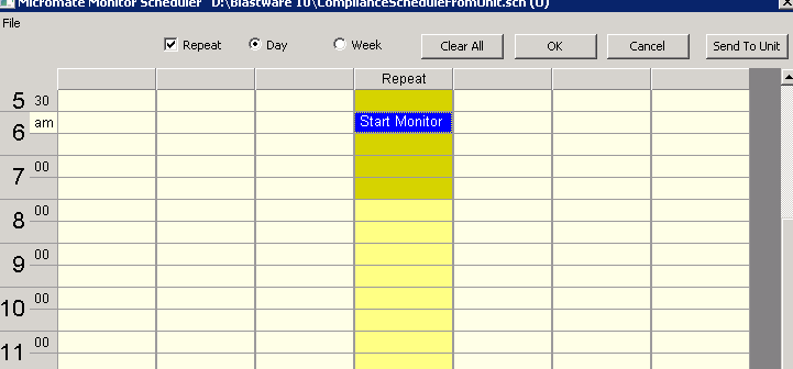
The following example shows a 7 day repeat blank scheduler template.
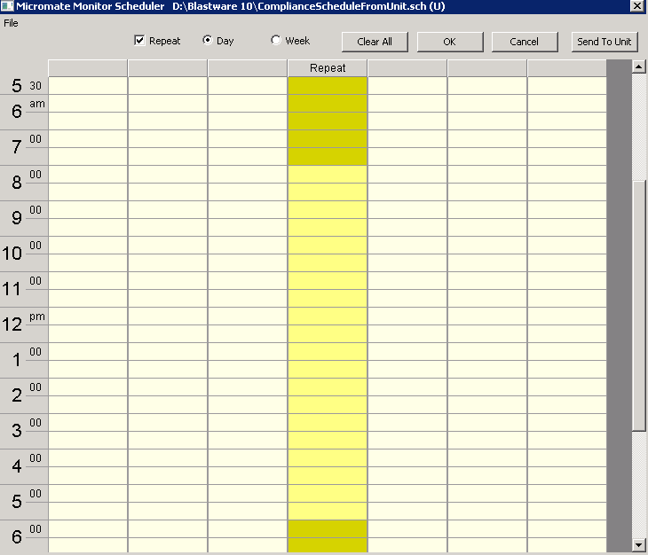
To activate a cell, click on a yellow cell that corresponds to the time you would like to activate.
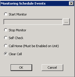
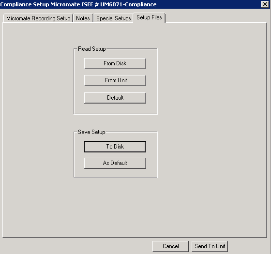
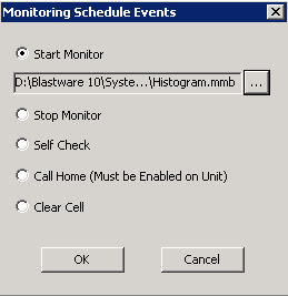
Start Monitor - Start Monitor will start the Micromate® in Monitor Mode. You must choose a Compliance Setup(.mmb) file that has been previously saved to your local or remote drive. If you have not saved a Compliance Setup file exit the Scheduler by clicking on the Cancel button in the Monitoring Schedule Events window and then clicking the Cancel button in the Monitor Scheduler window. If you have already setup the Compliance Setup on the Micromate® click the Setup Files tab under Compliance Setup and then click To Disk under Save Setup. If you have not already setup the Micromate® Compliance Setup how you want, go back to the Micromate® Recording Setup tab and configure the Recording Setup, then configure the Notes tab and the bottom half of the Special Setups tab before returning to the Setup Files tab to Save the Setup to Disk.
Once you have the Compliance Setup file saved to disk, you will be able to browse for the setup file and select it so that it shows in the Start Monitor file selection box.
Click OK to load the Start Monitor command into the cell. Keep in mind that if you make a mistake you can clear an inidividual cell by clicking the cell and choosing Clear Cell, then click OK.
If you are doing 24 hours a day, 7 days a week Histogram or Histogram Combo Monitoring your setup is done. All you need is one Start command in the scheduler. Each day at the Start time the Histogram file from the previous day will be closed out and a new Histogram file will be started. The Micromate® will perform an AutoCall Home before the new Histogram file is started which will upload the previous Histogram to the server and clear the Micromate®'s memory.
To save the scheduler to the unit, click the Send to Unit button in the top right corner of the Monitor Scheduler window. It is a good idea to save the scheduler(.sch) file as a backup and/or for future use.
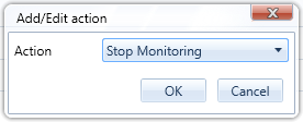
Stop Monitoring - If you are only monitoring during the day, for example 6am-6pm, you will also want to include a Stop time in your scheduler. To do this, double click on the cell corresponding to 6pm and then choose Stop monitor. The Micromate® will also perform an AutoCall Home at this time if you have choosen to Call Home After an Event under Remote Access>AutoCall Home>Setup Unit in Blastware. This feature designates all Scheduler Events as AutoCall Home Events, not just vibration or microphone triggers.
AutoCall Home - The AutoCall Home command in the scheduler is really only for Histogram only monitoring where you will not have waveform events during your monitoring period to trigger an AutoCall Home session. The Start and Stop commands will trigger an AutoCall Home for most situations other than Histogram only monitoring.
Scheduler - Series IV PRO4/PRO6
How do I use the Scheduler on the Series IV Minimate PRO4 or PRO6?
At this time, uWave Monitoring Systemsdoes not recommend using the Monitor Scheduler for the Series IV Minimate PRO4/PRO6 units as it is unstable. Please use the Call Home times in Blastware under Remote Access>AutoCall Home>Setup Unit to schedule AutoCall Home times for the Series IV units. Instantel is currently working on a firmware update for the Series IV units and we hope to see a firmware update in 2016 to correct the scheduler. Thank you for your patience.
THOR
THOR Download
THOR Download
Download THOR now.
Download the THOR specifications sheet here.
Download the THOR Advanced specifications sheet here.
Download the THOR Operator Manual here.
Add a Unit
How do I add a Micromate® or PRO unit to THOR?
Auto Discovery - To have THOR auto detect your locally attached unit make sure you have "Auto Discover Connected Units" checked under Preferences. If "Auto Discover Connected Units" is currently off, check the box next to the "Auto Discover Connected Units" setting and click Apply. When you connect a Micromate® using the USB to PC cable or a PRO unit using the Ethernet cable THOR will automatically load the unit into the Unit tab of THOR.
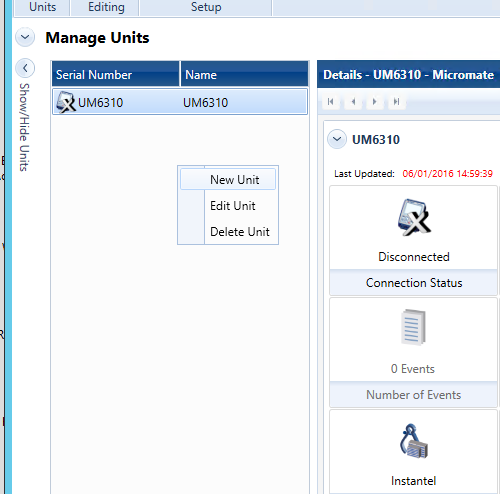
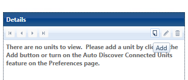
Manually adding a unit - On the Unit tab in THOR right click under the left section of the window beneath Serial Number and Name, now click New Unit. You can also add a new unit by click the Add button in the right corner of the Details section of the Unit tab, the Add button resembles a document with the lower left corner upturned.
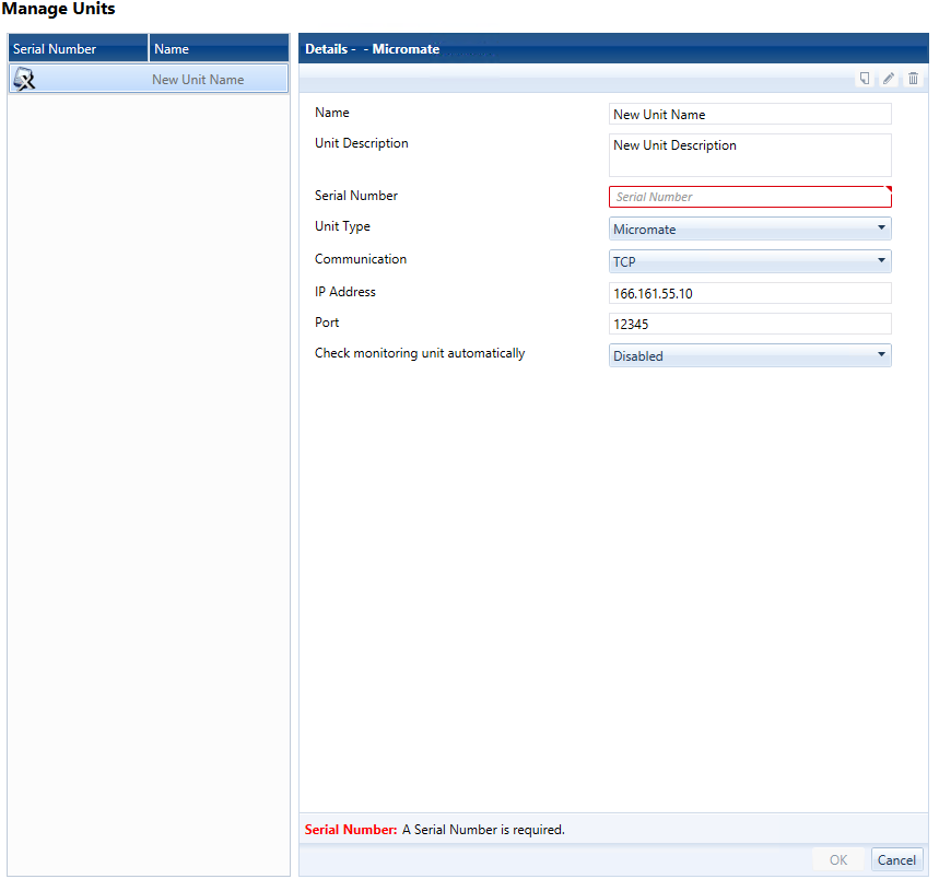
Enter a Name and Unit Description, Serial Number and Unit Type.
Local Units - Choose Serial, then enter the port number that the USB drive has installed the virtual COM port on. For COM5, enter '5' not 'COM5', if you are using a PRO4 you can also set the Baud Rate, 115200 offers the best performance.
Remote Units - Choose TCP, enter the IP address for the modem and the modem device port.
Check Monitoring Unit automatically - This setting tells THOR how often to check the connection and status of the monitoring unit. For locally connected units, choose the setting which suites your use best. It is recommended to leave this Disabled for remote units in order to minimize the communication frequency and remote data charges. When all the information is correct click OK to add the unit.
Add or Edit a Compliance Setup
How do I add a new compliance setup or edit a compliance setup that I have currently on the Micromate® or PRO unit?
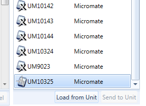
With the THOR application open, click the Unit tab and then click on the Compliance button to access the Compliance Setup module. If you have configured a compliance setup file on the Micromate® or PRO unit you may import this into THOR by selecting the specific Unit and then click on the Load from Unit button in the lower right corner of the window.
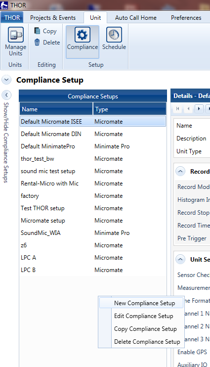
If you would like to create a new compliance setup file, right click in the Compliance Setups column and select New Compliance Setup. OR click the Add button under the Details section of the Compliance Setup window. If you want to edit the compliance setup that you just loaded or to edit an existing compliance setup file you may either select the setup file and right click and then click on Edit Compliance Setup or click the Edit button in the Details section of the Compliance Setup window. Once you have made changes click OK, then choose the unit to update and click Send to Unit.
THOR Scheduler
How do I configure the scheduler using THOR?
uWave Monitoring Systemsrecommends using THOR to configure the scheduler for the Micromate®. Using the scheduler on the PRO4 or PRO6 is not currently recommended.
First make sure you have followed the previous section Add or Edit a Compliance Setup so that you have a unit setup file for the scheduler to use.
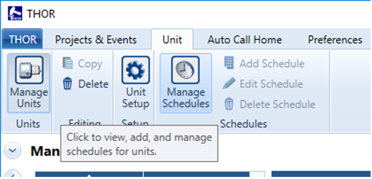
In THOR, click on the Unit tab and then click the Manage Schedules.
To add a new schedule, either right click in the Schedules section on left side of the window and then click New Schedule Setup
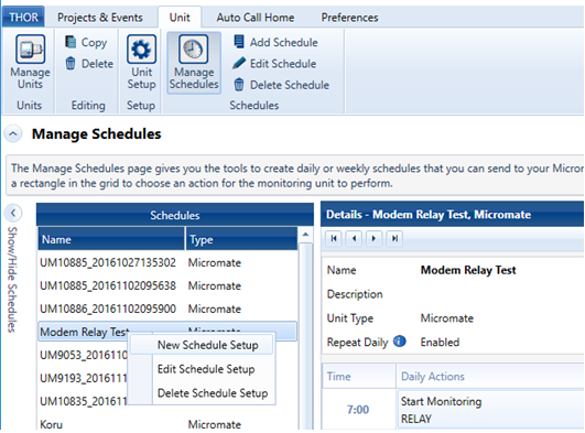
or click the paper icon at the top right corner of the Details section of the window.

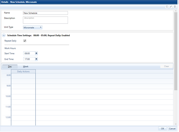
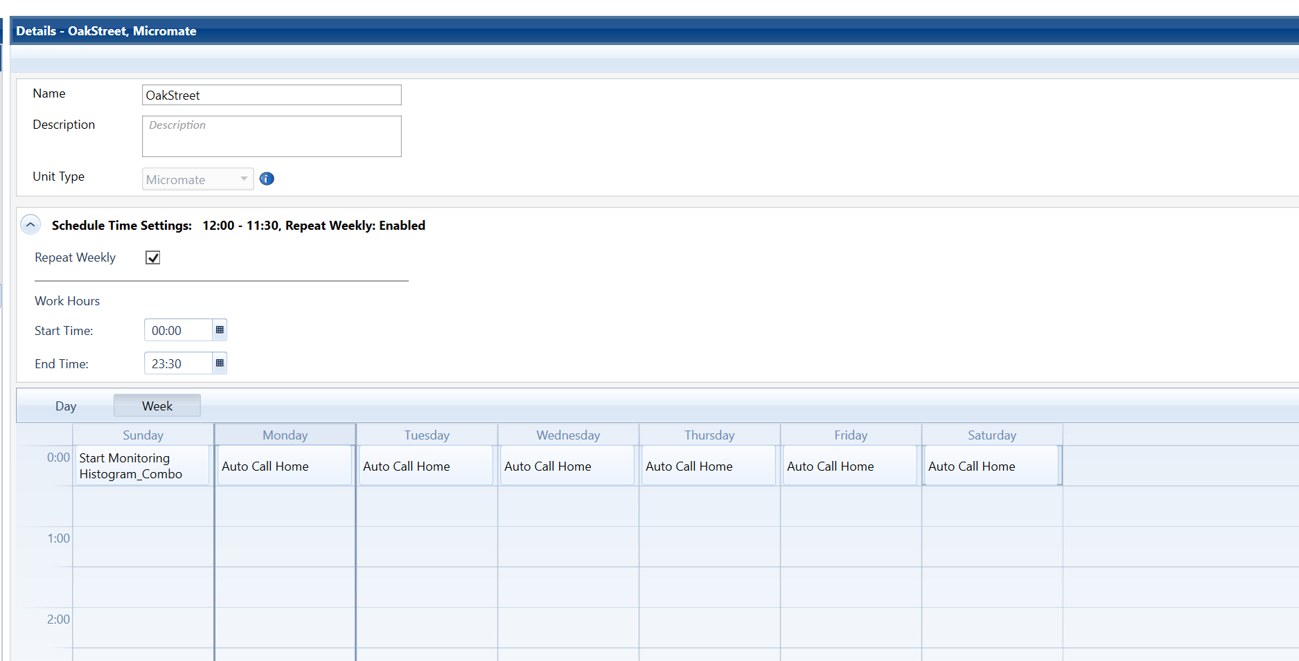
Enter a Name and Description for the scheduler file, select Micromate® for the Unit Type. Under Schedule Time Settings, check the Repeat Daily checkbox so that the same schedule will be run each day. If you wish to narrow the scheduler work hours you can select the Start Time and End Time. Select Day, or Week, if you need scheduler flexibility, such as 5 or 6 day per week monitoring.

24 hour monitoring example, repeat daily
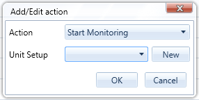
Click in the cell corresponding to the Start Monitoring time. Select the unit setup file to use for monitoring and then click OK. If you have not created the unit setup file you wish to use for monitoring, click the New button and create a unit setup file first. For 24 hour monitoring only a Start Monitoring command is necessary so click the OK button at the bottom right corner of the Details section and click OK in the confirmation window.
24 hour monitoring example, repeat weekly
Click the Weekly label in the Scheduler Details to change to a weekly view. Configure the scheduler as shown in the screenshot below. If you have not created the unit setup file you wish to use for monitoring, click the New button and create a unit setup file first. For 24 hour weekly monitoring only one Start Monitoring command is necessary followed by Auto Call Home commands at midnight on the following days. Click the OK button at the bottom right corner of the Details section and click OK in the confirmation window.
8 hour monitoring example
Click in the cell corresponding to the Start Monitoring time. Select the unit setup file to use for monitoring and then click OK. If you have not created the unit setup file you wish to use for monitoring, click the New button and create a unit setup file first. Click the cell corresponding to the Stop Monitoring command and then choose Stop Monitoring and click OK. Click the OK button at the bottom right corner of the Details section and click OK in the confirmation window.
Make sure you have the correct unit selected in the Units column on the right side of the window and then click the Send to Unit
Micromate
Micromate - Reboot
The Micromate is not responding, is there a way to reset or reboot it?
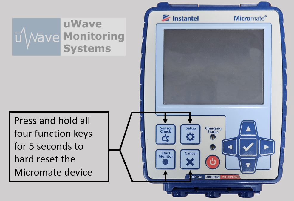
To reboot the Micromate, hold down the four function keys labeled Sensor Check, Setup, Start Monitor and Cancel simultaneously for at least 5 seconds. The Micromate will reboot. This action does not affect the memory or any settings.
Micromate Reboot buttons - Press all four function buttons at the same time.
AutoCall Home
AutoCall Home Unit - Series III and PRO4 Setup
How do I setup my Instantel Minimate Plus, Blastmate III or Minimate PRO4/6 for AutoCall Home?
You should first make sure your seismograph is compatible with AutoCall Home. Series III Minimate Plus and Blastmate III units above serial number 6000 have AutoCall Home. All Series IV Minimate PRO4 and Minimate PRO6 units as well as the new Micromate® have AutoCall Home. Series II Minimates, Blastmate II's and Minimate Blasters do NOT have the AutoCall Home feature.
You should always use Blastware to perform the initial setup of AutoCall Home on the unit. The factory default configuration on units with AutoCall Home is to use an old dial-up modem. 99.9% of installations will not use the factory default setting for AutoCall Home so you must configure this using Blastware.
When you have established communications with your seismograph either locally or remotely you will need to verify if the unit is monitoring or not. If the unit is monitoring, first go to Unit>Monitor to pull up the Monitor Status window. Click Stop monitoring and then click Cancel. Once your unit is idle, to access the Auto Call Home configuration window, Click on Remote Access>AutoCall Home>Setup Unit.
This should display the Call Home Setup window:
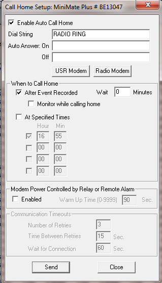
Enable AutoCall Home by placing a check in the checkbox labeled: Enable AutoCall Home. Next, click the Radio Modem Button to set the Dial String to RADIO RING. You should use this setting for all cellular modem installations.
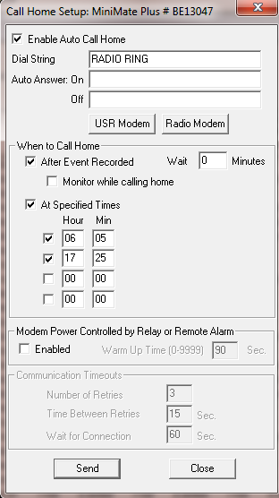
If you are using AutoCall Home as an alert system in Continuous mode or Histogram Combo mode, under When to Call Home, you will want to check the After Event Recorded checkbox. Note that this does not work in Histogram mode. Typically you will leave the default of Wait 0 minutes, but if you are using Continuous mode and you expect another event within 5 minutes you should add a delay of 10 minutes so that you do not miss an event. Alternately, if you are using Continuous Mode you can use the Monitor while calling home checkbox to stop the AutoCall Home process if another event occurs at or above the trigger level. This will stop the first event from transfering, it will record the second event and then AutoCall Home will transfer both events. Keep in mind that if the Monitor while calling home feature is used, the log file will not be transferred during the AutoCall Home process and the memory will not be cleared.Nonstop monitoring is not supported in Histogram Combo mode for Series III units, use the PRO or Micromate® instead. If you use the Monitor while calling home feature you must set a time under At Specified Times so the memory will have a chance to clear, otherwise, once the memory is full the unit will stop taking data.
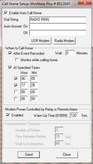
If you are using an RV50, GX400 or LS300 cellular modem with your Instantel monitor, you may have a need to use the internal relay in these modems. In this case, you would Enable this feature and include an initialization time in seconds.
AutoCall Home Unit - Micromate® Setup using THOR
How do I setup my Instantel Micromate® for AutoCall Home using THOR?
Use THOR to perform the initial setup of AutoCall Home on the unit. AutoCall Home is disabled under the factory setup.
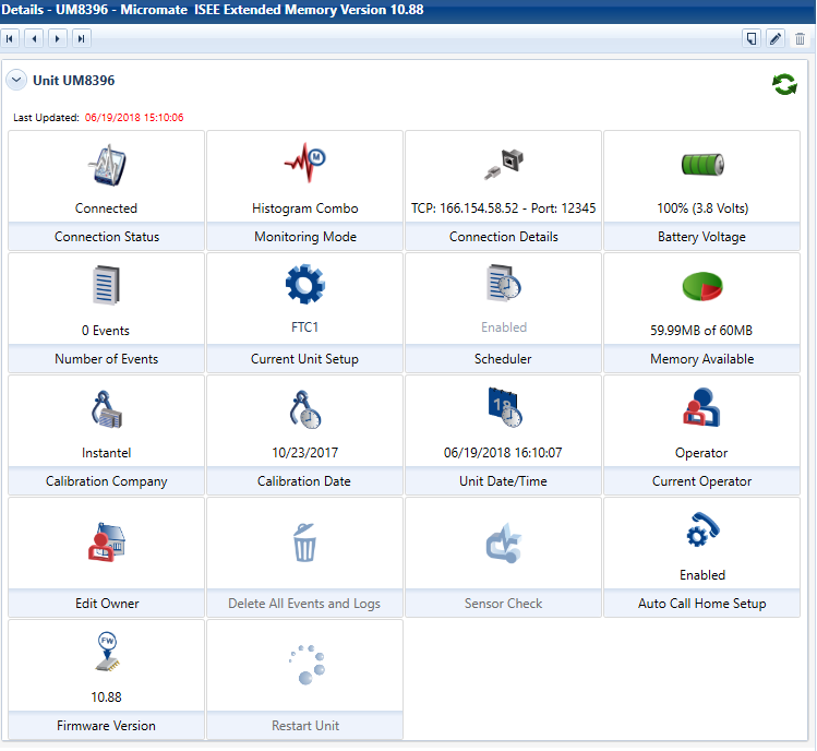
When you have established communications with your Micromate® either locally or remotely using the Unit tab in THOR, click on the unit serial number in the unit listing on the left side of the THOR window to bring up the Unit Details menu. The Auto Call Home Status is displayed for the connected unit.
Now click on the AutoCall Home icon:
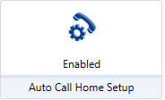
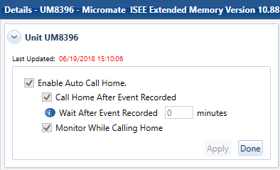
Enable AutoCall Home by placing a check in the checkbox labeled: Enable AutoCall Home.
If you are using AutoCall Home as an alert system in Continuous mode or Histogram Combo mode, you will want to check the Call Home After Event Recorded checkbox. Note that this does not work in Histogram mode. Use the Monitor Scheduler to schedule an AutoCall Home time. Typically you will leave the default of Wait After Event Recorded 0 minutes, but if you are using Continuous mode and you expect another event within 5 minutes you should add a delay of 10 minutes so that you do not miss an event. Alternately, you can use the Monitor While Calling Home checkbox to transfer waveform events while the Micromate® is still recording the histogram. Keep in mind that if the Monitor While Calling Home feature is used, the log file will not be transferred during the AutoCall Home process and the memory will not be cleared. If you use the Monitor While Calling Home feature you must also set a time in the Scheduler so the memory will have a chance to clear, otherwise, once the memory is full the unit will stop recording data.
Limitations when using Monitor While Calling Home feature for 24 hour monitoring:When using Monitor While Calling Home, true 24 hour recording is not possible due to the instability of the weekly scheduler mode. For this reason the daily scheduler must be used. When using the daily scheduler and Monitor While Calling Home 23.5 hour monitoring can be accomplished by setting a Start time of 00:00 and a Stop time of 23:30. If you only set a Start time of 00:00 then the memory will never be cleared and the monitor log will not be uploaded. This may be OK for short term projects but the memory will fill up after a certain time period depending on your Micromate®'s free memory.
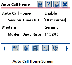
The Micromate® unit must be setup separately from the software so that it uses the correct USB port to send data to the modem or to the connected computer depending on which device you choose. Note that you will not be able to contact the unit remotely if the Modem type is set to USB to PC and the unit is monitoring.The default Session Timeout Setting of 30 minutes is recommended.
If you are using an RV50, GX400 or LS300 cellular modem with your Instantel monitor, you may have a need to use the internal relay in these modems. Contact uWave Monitoring Systemsand we can preconfigure your modem for use in low power mode.
Long Term Maintenance
Battery Maintenance
How do I maintain my seismograph battery?
We recommend keeping your Instantel seismograph plugged in using the AC adapter when not in use. Leaving the instrumentation on charge will not damage the battery. It provides a trickle charge to keep the battery fully charged.
Test your AC adapter annually to ensure it produces the proper voltagae.